Network
A computer network can be described as a system of interconnected devices that can communicate using some common standards (called protocols). These devices communicate to exchange resources (e.g. files and printers) and services.
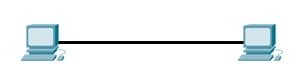
Network of two computers only
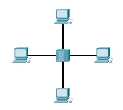
A network with a hub
LAN
Local Area Network (LAN) is commonly used to describe a network of devices in a limited area (a house, office, building…). This type of network is usually capable of achieving high data transfer rate (up to 10 Gbps!) at low cost. A typical SOHO (small office/home office) LAN consist of PCs, printers, switches, routers, and cabling that connects all these devices together.
Typical LAN

Some of the most popular LAN technologies are Ethernet, Token Ring and FDDI. Most LAN networks use TCP/IP to communicate. Twisted-pair cabling is usually used in a LAN. Ethernet is by far the most popular wired LAN technology. It defines wiring, signaling, connectors, frame formats, protocol rules, etc. Most modern LANs also support the wireless LAN (WLAN) technology, defined by the IEEE 802.11 standards. WLANs use radio waves instead of wires or cables for links between devices.
The term metropolitan area network is used to describe a network in a single metropolitan area, hence the name. This type of network is usually bigger than a LAN and smaller than a WAN. An example of this type of network would be a network that connects two company offices inside the same city.
OSI & TCP / IP models
OSI (Open Systems Interconnection) Model
It was designed to be a reference model for describing the functions of a communication system. The OSI model provides a framework for creating and implementing networking standards and devices and describes how network applications on different computers can communicate through the network media.

The layers are usually numbered from the last one, meaning that the Physical layer is considered to be the first layer. Most people learn the mnemonic “Please Do Not Throw Sausage Pizza Away“.

Brief description of each of the layers of the OSI model.
Physical – defines how to move bits from one device to another. It details how cables, connectors and network interface cards are supposed to work and how to send and receive bits.
Data Link – encapsulates a packet in a frame. A frame contains a header and a trailer that enable devices to communicate. A header (most commonly) contains a source and destination MAC address. A trailer contains the Frame Check Sequence field, which is used to detect transmission errors. The data link layer has two sublayers:
Logical Link Control – used for flow control and error detection.
Media Access Control – used for hardware addressing and for controlling the access method.
Network – defines device addressing, routing, and path determination. Device (logical) addressing is used to identify a host on a network (e.g. by its IP address).
Transport – segments big chunks of data received from the upper layer protocols. Establishes and terminates connections between two computers. Used for flow control and data recovery.
Session – defines how to establish and terminate a session between the two systems.
Presentation – defines data formats. Compression and encryption are defined at this layer.
Application – this layer is the closest to the user. It enables network applications to communicate with other network applications.

TCP/IP model
It describes general guidelines for designing and implementing computer protocols. It consists of four layers: Network Access, Internet, Transport, and Application.

Here is a brief description of each layer:
Link – defines the protocols and hardware required to deliver data across a physical network.
Internet – defines the protocols for the logical transmission of packets over the network.
Transport – defines protocols for setting up the level of transmission service for applications. This layer is responsible for reliable transmission of data and the the error-free delivery of packets.
Application – defines protocols for node-to-node application communication and provide services to the application software running on a computer.
Differences between OSI and TCP/IP model
OSI model prescribes the steps needed to transfer data over a network and it is very specific in it, defining which protocol is used at each layer and how. The TCP/IP model is not that specific. It can be said that the OSI model prescribes and TCP/IP model describes.
TCP (Transmission Control Protocol ) / IP (Internet Protocol) suite of protocols
It provides an end-to-end connectivity by specifying how data should be packetized, addressed, transmitted, routed and received on a TCP/IP network. This functionality is organized into four abstraction layers and each protocol in the suite resides in a particular layer. Some of the protocols included in the TCP/IP suite are:
ARP (Address Resolution Protocol) – used to associate an IP address with a MAC address.
IP (Internet Protocol) – used to deliver packets from the source host to the destination host based on the IP addresses.
ICMP (Internet Control Message Protocol) – used to detects and reports network error conditions. Used in ping.
TCP (Transmission Control Protocol) – a connection-oriented protocol that enables reliable data transfer between two computers.
UDP (User Datagram Protocol) – a connectionless protocol for data transfer. Since a session is not created before the data transfer, there is no guarantee of data delivery.
FTP (File Transfer Protocol) – used for file transfers from one host to another.
Telnet (Telecommunications Network) – used to connect and issue commands on a remote computer.
DNS (Domain Name System) – used for host names to the IP address resolution.
HTTP (Hypertext Transfer Protocol) – used to transfer files (text, graphic images, sound, video, and other multimedia files) on the World Wide Web.
The following table shows which protocols reside on which layer of the TCP/IP model:

Encapsulation
The term encapsulation is used to describe a process of adding headers and trailers around some data. This process can be explained with the four-layer TCP/IP model, with each step describing the role of the layer.
Example
The email is sent from the Application layer to the Transport layer.
The Transport layer encapsulates the data and adds its own header with its own information, such as which port will be used and passes the data to the Internet layer
The Internet layer encapsulates the received data and adds its own header, usually with information about the source and destination IP addresses. The Internet layer than passes the data to the Network Access layer
The Network Access layer is the only layer that adds both a header and a trailer. The data is then sent through a physical network link.
Graphical representation of how each layer add its own information

Each packet (header + encapsulated data) defined by a particular layer has a specific name:
Frame – encapsulated data defined by the Network Access layer. A frame can have both a header and a trailer.
Packet – encapsulated data defined by the Network layer. A header contains the source and destination IP addresses.
Segment – encapsulated data as defined by the Transport layer. Information such as the source and destination ports or sequence and acknowledgment numbers are included in the header.
Data encapsulation in the OSI model
Just like with the TCP/IP layers, each OSI layer asks for services from the next lower layer. The lower layer encapsulates the higher layer’s data between a header (Data Link protocols also add a trailer). While the TCP/IP model uses terms like segment, packet and frame to refer to a data packet defined by a particular layer, the OSI model uses a different term: protocol data unit (PDU). A PDU represent a unit of data with headers and trailers for the particular layer, as well as the encapsulated data. Since the OSI model has 7 layers, PDUs are numbered from 1 to 7, with the Physical layer being the first one.
Graphical representation of all the PDUs in the OSI model:
